Most modern clocks opt for digital displays, but there’s still an undeniable charm in the traditional analog format with hour, minute, and second hands. This project blends the best of both worlds by presenting an analog clock—minus the physical hands—using a WS2812 LED ring and precise radio time synchronization via the DCF77 signal.

Instead of mechanical components, this clock uses a circular arrangement of 60 individually addressable WS2812 RGB LEDs (commonly known as Neopixels) to indicate time. The second, minute, and hour "hands" are represented by LEDs in red, green (flashing), and blue respectively, providing a visual yet modern approach to the classic analog style.
Timekeeping Powered by the DCF77 Atomic Signal
At the heart of the synchronization lies the DCF77 receiver module. This component picks up longwave time signals from Mainflingen, Germany, transmitted at 77.5 kHz. These signals are encoded with current time data, and this project includes a custom-written ISR (Interrupt Service Routine) to decode the pulses with precise timing accuracy.

While DCF77 libraries do exist, the creator of this project took a low-level approach, building a robust ISR that switches between rising and falling edges to measure pulse durations. Each pulse corresponds to a binary bit, and a complete time message takes one full minute to decode—assuming clean signal reception.
Due to the increasing prevalence of electromagnetic interference (EMI), the code is designed to handle noise gracefully. It distinguishes between synchronized (green), unsynchronized (blue), and fallback/internal timekeeping mode (red), adjusting the clock face color accordingly. This makes it immediately clear whether the time is accurate or being simulated internally.
Hardware and Setup
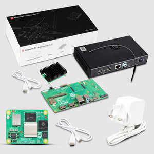
The project uses:
-
Arduino UNO (either R3 or R4, though R4 is overkill)
-
DCF77 Receiver Module
-
WS2812 60-LED Ring
The LED ring is segmented into four parts, which need to be soldered together. Careful physical alignment is essential to ensure LED 0 starts at the 12 o'clock position. The code provides a ROTATION constant for adjustment.
Additionally, mounting tips are shared to reduce interference—like keeping the DCF antenna away from the Arduino, as microcontrollers emit noise that could affect signal reception.
Software and Behavior
The Arduino sketch is optimized for low memory usage, consuming around 6 KB of ROM and 640 bytes of RAM on an UNO R3. It does not rely on external libraries for DCF decoding, but does utilize Adafruit’s NeoPixel library for LED control.
The code handles error detection, parity checks, and continues internal timekeeping in case of signal loss. It updates every second, rotating the relevant LEDs and refreshing the clock face visually.
This project combines radio-frequency timekeeping with vibrant LED-based visualization in a unique and educational build. It’s a great demonstration of using interrupts, signal decoding, and visual feedback for real-world embedded systems.
If you're a maker looking for a blend of retro charm and modern tech, this analog LED clock is a rewarding project worth building.
Source - Klausj