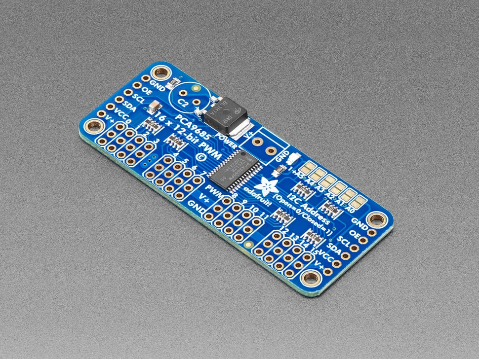
This PWM and Servo driver breakout is the perfect solution for controlling multiple servos or LEDs with precise PWM output. It’s an ideal tool for building robots, like a hexapod walker, or creating art with many moving parts. With a limited number of PWM outputs on your microcontroller, this breakout board expands your possibilities.
The I2C-controlled PWM driver with a built-in clock makes it incredibly efficient, as it doesn't require continuous signaling from your microcontroller. This means your microcontroller is free for other tasks while the driver runs independently.
Features include:
- Control 16 PWM outputs with just two pins, and chain up to 62 breakouts, giving you up to 992 PWM outputs.
- 5V compliance allows control from 3.3V microcontrollers, with safe output up to 5.5V—ideal for high-voltage LEDs like common-anode white or blue LEDs.
- Adjustable PWM frequency up to 1.6 kHz.
- 12-bit resolution for each output, perfect for precise servo control with about 4µs resolution at a 60Hz update rate.
- Configurable push-pull or open-drain output options.
- A dedicated output enable pin to quickly disable all outputs.
The breakout board is packed with helpful extras:
- Terminal block for power input (or use the 0.1" breakouts on the side).
- Reverse polarity protection on the terminal block.
- Green power-good LED for easy status check.
- 3-pin connectors in groups of 4, so you can plug in 16 servos or LEDs at once (slightly wider than 0.1" for stacking).
- "Chainable" design to easily expand your setup.
- A spot for a large capacitor on the V+ line for extra stability (if needed).
- 220-ohm series resistors on output lines to protect and simplify LED driving.
- Solder jumpers for selecting one of 6 address pins.
This fully assembled breakout board includes:
- 4 pieces of 3x4 male straight header (for servo/LED plugs).
- 2-pin terminal block (for power).
- 6-pin 0.1" header (for breadboard use).
Assembly is simple and beginner-friendly, with just a small amount of soldering required to attach the headers, making it a 15-minute task. For added flexibility, right-angle 3x4 headers are also available for purchase.
Technical Details:
- Dimensions (without headers or terminal block): 2.5" x 1" x 0.1" (62.5mm x 25.4mm x 3mm)
- Weight (without headers or terminal block): 5.5 grams
- Weight (with 3x4 headers & terminal block): 9 grams
- I2C 7-bit address range: 0x40-0x7F, selectable using jumpers
- Additional resources: Datasheets, EagleCAD PCB files, Fritzing object, and more available in the tutorial
Revision History:
- December 20, 2022: Updated PCB with Adafruit Pinguin for a more legible silkscreen. Both the new and older versions are functionally identical, with only a difference in the silkscreen design.
- February 16, 2015: Replaced polarity-protection transistor with a more robust version. Functionality remains unchanged.


