Overview
IoT-Pi is an industrial board that consists of onboard RP2040, ESP8266 WIFI(ESP-12E) and RS-485 communication that can control up to 4/6 appliances/devices on a load of, photo-coupling isolation Optocoupler EL357NC, allowing users to safely control high voltages or current devices. IoT-Pi makes appliances smart, which users can operate via the PiRelay app on their electronic device. IoT-Pi also consists of additional GPIOs pins for connecting extra Hardware to this board.
RS485
RS-485 is an industrial specification that defines the electrical interface and physical layer for point-to-point communication of electrical devices. The RS-485 standard allows for long cabling distances in electrically noisy environments and can support multiple devices on the same bus. It is a serial communication protocol and is a ubiquitous device interface.
Feature
- Onboard RP2040 with Pinout
- ESP8266 RS485
- 4/6Ch- Relays
- Isolated RS485 Port
- Isolated Power Supply
- Optocoupler Isolation
- Onboard AC/DC Convertor
- 4/6 relay indicators, 1 programmable status LED, power led
- Power Supply - Screw Terminal/ USB Micro/ Hi link AC DC (HLK5705)
- Programmable RP2040 Pins - 5 GPIO
Specifications
- Channel - 4 CH
- Operating Voltage - 5V
- AC Control Voltage - 7A / 250V
- DC Control Voltage - 10A / 30V
- High-quality Relays.
- Dimensions - 6.5cm x 5.5cm
Hardware Details
Let’s take a closer look at our IoT-Pi 4/6ch relay board, and see what other hardwares are present on this board

RP2040
Raspberry Pi RP2040 Microcontroller Chip is the debut microcontroller from Raspberry Pi. It brings high performance, low cost, and ease of use to the microcontroller space. The RP2040 has a large on-chip memory, symmetric dual-core processor complex, deterministic bus fabric, and rich peripheral set. It's augmented with a unique Programmable I/O (PIO) subsystem and provides unrivaled power and flexibility.
ESP8266
The ESP8266 WiFi Module is a self contained SOC with integrated TCP/IP protocol stack that can give any microcontroller access to your WiFi network. The ESP8266 is capable of either hosting an application or offloading all WiFi networking functions from another application processor.
Relays
The IoT-Pi 4ch board has 4 relay modules for connecting the four different appliances or any devices you want to control through our IoT-Pi board. In IoT-Pi 6ch has six relays for controlling the six outputs.
AC/DC Converter
It is the onboard power supply module for this board. Through this we can power-up our IoT-Pi board by providing AC supply.
USB Port, Reset Button and Boot Button
We can power-up this board through AC supply as well as through Micro-USB port. It is also used for debugging python programmes in our IoT-Pi board. Reset button is for rebooting or restarting the controller and so the IoT-Pi board. Boot button is used for updating new firmware to our RP2040.
Power Port and Power Isolator
Power port is provided for powering-up RS485 sender modules, by connecting Positive terminal to positive of sender and negative terminal of IoT-Pi board to negative terminal of sender module.Power Isolator is used to provide isolation between RS485 power supply and rest of components.
RS485
It is used to communicate with RS485 sender by connecting its A-terminal and B-terminal to A-terminal and B-terminal of the sender module respectively. Power port should be connected in the right direction (positive terminal to positive and negative terminal to negative of sender and receiver) in boards.
Additional GPIO
It is provided for interfacing other peripherals (such as sensors) to this board.
Hook Up Guide


Steps To Follow for Working with IoT-Pi Boards
Before starting with this board you have to go on github page and search for sbshop under this search for IoTPi and follow the steps below: Step.1 - Download the Zip file of IoTPi package and extract it in your computer system, for this click on code—>download Zip (Highlighted with Red)

Step.2 - After downloading and extracting the Zip file you will get the following files under the “IoTPi-main” folder

Step.3 - After that open the folder IoTPi 4-channel if you have our 4-channel board or if you have 6-channel board then open IoTPi 6-channel folder. Under this you get two python files as shown in below image

Step.4 - File “home_automation_4ch” is the main file and “IoTPi” is the library file for our IoTPi boards. To open these files you should have Thonny IDE installed in your system, If you don’t have Thonny IDE follow the link below to install it. Click here
Step.5 - First Open both files in your IDE and connect your IoTPi board to your computer via using micro-usb cable.

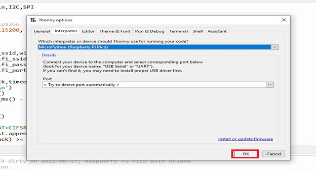
Step.6 - Now select the interpreter by clicking on “Run” button in IDE and follow the image instructions below


Step.7 - After selecting the interpreter click on the “Stop” button for restarting your board. If your board is properly connected you will get the RP2040 information as , shown below

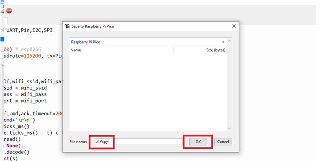
Step.8. Now click on “IoTPi” file and save it in your RP2040, for this click on “file” (upper left corner in your IDE) under that click on “save as” you will get a window asking for where you want to save your copy file, click on “Raspberry Pi PICO” and save it by naming it “IoTPi” and click on “Ok”. Your file will be saved in RP2040 of your IoTPi Board.


Step.9 - After that you have to save the code file (home_automation_4ch) in RP2040 same as the library file(step.5), only change is you have to save it by naming it “main.py” and then click on “Ok”. You can also see that your library file already saved here that you recently saved in it.

Step.10 - Now, both the library and main file are saved in your board and it is ready to control relays of it and so on appliances that you want by providing the command accordingly.

Downloading Android Application As in previous steps we completed the code saving and other important steps to work with the IoTPi board. Now in this section we will learn how to control it.
Step.1 - In the IoTPi_main folder you will also get a folder named with “Android Application” 
Step.2 - Open this folder and under this you will get a .apk file named with “IoTPi.apk” download and install this application in your android phone for controlling your IoTPi Board.

Step.3 - After installing the app, open it and you will get the interfaces as following below


Step.4 - For connecting this application to your board provide IP address of your WiFi which your using at that time, in my case my it was 192.168.43.18 as shown below

Step.5 - Initially the button setting should be as shown in below image for giving ON/OFF commands. After that you can change it according to your code.

Communication Using RS485 The IoTPi board also has the feature of rs485. You can use this feature by making one of your boards as the sender and another one as receiver. Fer this follow the steps below
Step.1 - Locate the RS485 directory inside the IoTPi_main folder and open it, inside this folder you will get a file named with “rs485_test”

Step. 2 - Open the “RS485_test” file and you will get two blocks of codes, one is for making a receiver and the other one is for making your board as a sender.
Step. 3 - Uncomment the sender code and save it in RP2040 of your board and now it is ready for working as a rs485 sender device.

Step.4 - Now, uncomment the receiver block of code(sender block should be commented this time) and save it in another board.

Step.5 - Now, your sender and receiver board is ready for communicating to each other by using rs485 protocol.
Step.6 - Connect to RS485 port of your boards as shown below and Power port should be connected in the right direction to a 5V dc power supply.


