
Overview
The Zero Barcode HAT for Raspberry Pi is a reliable and small barcode scanner board that includes a buzzer, 1.14" LCD screen, micro-USB port, and DE2120 scanner module. It can scan 20 various barcode types in the 1D and 2D symbology segments, including barcodes and QR codes. By using the on-board camera for image processing, everything from UPC codes to QR codes may be recognized and decoded.
Feature
- 1- Micro USB Connector for USB HID Interface and Virtual COM port
- A.1D Symbologies
- UPC-A
- UPC-A
- UPC-E
- EAN-8
- EAN-13
- Code 128
- GS1-128
- Code 39
- Interleaved 2-of-5
- Matrix 2-of-5
- Industrial 2-of-5
- Coda-bar
- MSI
- GS1 Data Bar
- Datalogic 2-of-5
- 2- Reads 20 different symbologies
- B.2D Symbologies
- QR Code
- Data Matrix
- PDF 417
- Micro PDF 417
- Aztec Code 3- LCD 1.14"
- 4- Scan Button
- 5- Buzzer for successful read
- 6- Control through RPi and Micro-USB also
6- LCD Features:
- A. 240×135 resolution, 65K RGB colors, clear and colorful displaying effect
- B. SPI interface, minimizes required IO pins
7- LCD Specifications:
- a. Operating voltage of 3.3v/5v
- b. Resolution 240 x 135 pixels
- c. Communication Interface 4-wire SPI
- d. Display size of 24.91 x 14.86mm
- e. IPS display panel
- f. Pixel Size 0.1101 x 0.1035mm
- g. ST7789 driver
- h. Dimension 35 x 32.00mm
Hardware Overview:
Let's take a closer look at the DE2120 scanner module as well as the other hardware present on this board

DE2120 Scanner Module
The DE2120 barcode scanner module from DYScan combines a CMOS camera with on-board image processing to identify and decode 20 different barcode symbologies in both 1D and 2D on a variety of mediums (paper, screen, etc.). The DE2120 also includes two user-configurable LEDs. One super bright white LED to help illuminate the scanning area and one red LED to project the red line like those found on laser-based scanners.
The DE2120 interfaces over USB Serial and TTL UART and can operate in several modes including USB Keyboard (default), USB COM, USB HID and TTL. Configure the communication modes and other settings by scanning barcodes or sending serial commands from the Scan Settings Manual.
When in USB Keyboard mode, the scanner behaves as a keyboard input (think your typical scanner on a Point of Sale system) and "types" the scanned barcode data followed by a carriage return. In USB-COM mode, the scanner behaves as a USB COM device and in TTL mode, the scanner operates as a TTL UART device to interface with a controller.
The module's two LEDs are also fully configurable to set behavior, brightness and simple on/off settings
Pinouts and Micro-USB Connection
The scanner module receives power either via the Micro-USB connector or from a regulated 3.3V source through the 3.3V pin. The scanner requires at least 190mA@3.3V to function. 5V from USB is regulated to 3.3V through an on-board 3.3V/600mA regulator.
Buzzer, Status LED and Trigger Button
We've routed the trigger pin to a pushbutton labeled SCAN, the status LED pin to a green LED and buzzer pin to a Piezo buzzer. Configure the Trigger and Buzzer just like everything else on the DE2120 using serial commands or barcodes from the Scan Settings Manual. Use the Trigger Button to initiate a scan when the DE2120 is in Trigger Mode (default). The buzzer defaults to play a tone on power-up and on a successful decode. The STAT LED illuminates on power-up and on a successful scan.
Reserved Pins of Zero Barcode HAT

Hardware Assembly:
After the hardware overview we are well aware with the hardware presents on the Zero Barcode HAT. Now, let’s get its assembling and connection and start scanning barcodes
USB Assembly

It is the easiest way to start working with Zero Barcode HAT by using a Micro-USB cable. When the bar coder uses USB communication interface, but the host application program receives data by serial communication, it can be set to USB virtual serial communication mode. This function needs to install the corresponding driver on the host.

When using Linux system, the device is / dev / ttyACMx and X is the device number. If only one USB COM device is connected to the system, it is: / dev / ttyACM0.
Zero Barcode HAT Assembly with RPi

The serial communication interface is a common way to connect barcode and host devices and can be used to connect host devices such as PC and POS. When using the serial communication interface of the barcode scanner, the barcode scanner and the host device must be completely matched in the configuration parameters of the serial communication protocol to ensure the accuracy of data transmit.


Serial Default: Rate 9600bps; Data 8, Stop 1, Parity none. You can change the baud rate of Barcode Scanner at any time according to your need. For this refer to the page number 25 of the Barcode manual provided.
Arduino Library
Arduino Examples
Python Package
Python Example
Steps to Follow For working with Zero Barcode HAT
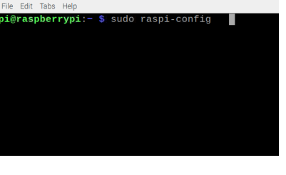
Steps for setup RPi to work with Zero-Barcode HAT: Step.1 - So, before start working with this module first you have to enable the SPI in raspberry pi, for this go to cmd line then type “sudo raspi-config” then go to ->interface option -> and enable the SPI by Following the below image steps
Step1.1 -

Step1.2 - SC2
As the above image showing a tab to configure your RPi, use arrow key of your keyboard and go to Interface options and press enter. After that keep following the image instruction till finish SPI configuration
Step1.3 - SC3

Step1.4 - SC4

Step1.5 - SC5

Step1.6 - SC6

After Finishing it-up reboot your RPi by typing reboot command and press enter
Step1.7 - SC7

Step.2 - Now, Setup your Pi Zero Barcode HAT for using with RPi:
Step 2.1 - After attaching the Barcode HAT to the RPi Zero, turn it on with a USB cable and begin configuring the barcode scanner for RPi.
Step 2.2 - First, you need to change the mode of the Zero Barcode HAT for this you need to scan the below barcode settings before running the code

Step 2.3 - In this step you have to Change the baud rate to (9600) for this you need to scan the below barcode by pressing the scan button on the Zero Barcode Hat. You can also change the baud rate according to your choice by referring to Barcode Manual provided.

Step 2.4 - The DE2120 is completely user configurable, you can configure many settings according to your requirement by referring the DE2120 Manual (Barcode manual) provided in this Repo.
Use Zero Barcode HAT without Raspberry Pi (Via USB Cable):
You can also use this barcode HAT simply with USB cable for reading (without any controller board). Step.1 - For this you simply need to scan the Below barcode and your barcode scanner is now ready to work in USB com mode.

Step.2 - In USB com mode, you have to open a notepad/word and scan any barcode or QR-code to get their number in your system. As shown in below image

